The Vortex Tube Separator is a device for chilling gas by expansion. The chilling process is more effective than the conventional expansion by the Joule Thomson valve.
As a result, using the vortex tube, lower hydrcarbon and water dewpoints can be achieved for the same pressure drop.
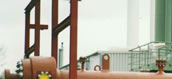
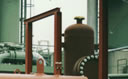
The Vortex Tube Separator is a long thin tube with a header, a throttle and
up to four inlet nozzles, with no moving parts. Maintenance requiremnts are
therefore very low.


The Vortex Tube Separator (VTSä) utilises two elementary physical concepts:
The gas is introduced into the Vortex Tube Separator through a header across tangential inlet nozzles. In most caese, depending upon the ratio of the inlet to outlet pressures, the gas will reach near sonic velocity as it passes into the vortex tube.
Due to the Hilsch effect both a warm and a cold gas fraction are created. During the near adiabatic expansion of the gas across the inlet nozzle, condensation of the gas components occur. The condensate is thrown to the outer wall of the Vortex Tube Separator and the liquid passes through drain holes at the bottom of the VTS to a separator
Simultaneously, gas moves from the wall to the centre of the tube where it
cools further. By removing the liquid phase from the tube wall it is possible
to obtain two discrete gas and liquid phases. Special internals at the opposite
end to the inlet enable the cold and warm gas streams to be separated. The
cold gas is diverted back by the throttle along the tube to the cold gas outlet.
The temperature gradient and the cold gas stream temperature increase the
liquid separation.
Both the cold and warm gas streams are thermodynamically superheated. Combing
the warm and cold gas is the normal mode of operation for the Vortex Tube
Separator (VTSä). (see figure 2)
Dependent upon the gas compositions and process conditions, a 15 - 20% weight additional condensate recovery may be expected compared to a typical JT process.
Potential Applications
The main areas for a Vortex Tube Separator installation are gas dewpointing, gas dehydration and condensate recovery/removal. Generally, gas wells or storages where typically JT valves are used and pressure drop is available, are good cases for potential installations
The Vortex Tube Separator can be used for gas dewpointing on sales or fuel gas systems utilising the same or reduced overall pressure drop.
In particular, utilising lower pressure drops the same dewpoint
is achievable on gas wells where reservoir pressure is declining and the sales
gas specification is in danger. The installation of a gas compressors could
be delayed if a Vortex Tube Separator were used.
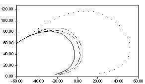
A performance curve of a VTS is shown in figure 3. The graph shows the phase
envelope of the untreated inlet gas and gas when dewpointed by the VTS, Joule
Thomson and Turbo expander. The inlet conditions and the pressure drop for
each unit / valve is the same (120 to 70bar), the grpah shows that the VTS
phase envelope falls between that of the Joule Thomson and the Turboexpander.
Operating requirements
Two major parameters must be satisfied for the safe operation of the Vortex Tube Separator.
Gasdehydration
The Vortex Tube Separator has been used for hydrocarbon dewpointing and simultaneous gas dehydration. The dehydration process is performed by injecting TEG directly upstream of the VTS. The TEG / gas contact temperature is lower than a typical contactor tower. The lower temperature favours a better adsorption equilibrium and therefore drier gas. The TEG and condensate are separated and the TEG regenerated for the recycling process. Due to the advantages in comparison to the gas dehydration with an absorber tower all dimensions and process datas downstream of the Vortex Tube Separator are appr. 60% smaller than usual.
In particular, dew points can be achieved using low glycol concentrations
(90 - 95%) and reduced flow rates. This reduces co-absorbed hydrocarbons and
aromatics and also allows glycol regeneration at lower temperatures (appr.
154°C), thereby reducing glycol degradation.
Turboexpander by-pass
Because of its improved condensate recovery relative to a Joule Thomson valve,
the VTS reduces the disturbance to the dawnstream equiptment resulting from
a turbine trip. This is particularly important where downstream gas treatment
plant is sensitive to reduce feed rates and changed conditions.